3.1. Pika Pie Development Board Quick Start
Today, we will not talk about the hard-core content of driver development and architectural principles. We will simply use the Pika Pie development board to play Python programming! Light up a “Life is too short, I use Python” achievement on the microcontroller!
3.1.1. Development board acquisition
If you don’t have a Pika Pie development board yet, you can buy it from the link below:
https://item.taobao.com/item.htm?spm=a21dvs.23580594.0.0.52de3d0dt7rqAx&ft=t&id=654947372034
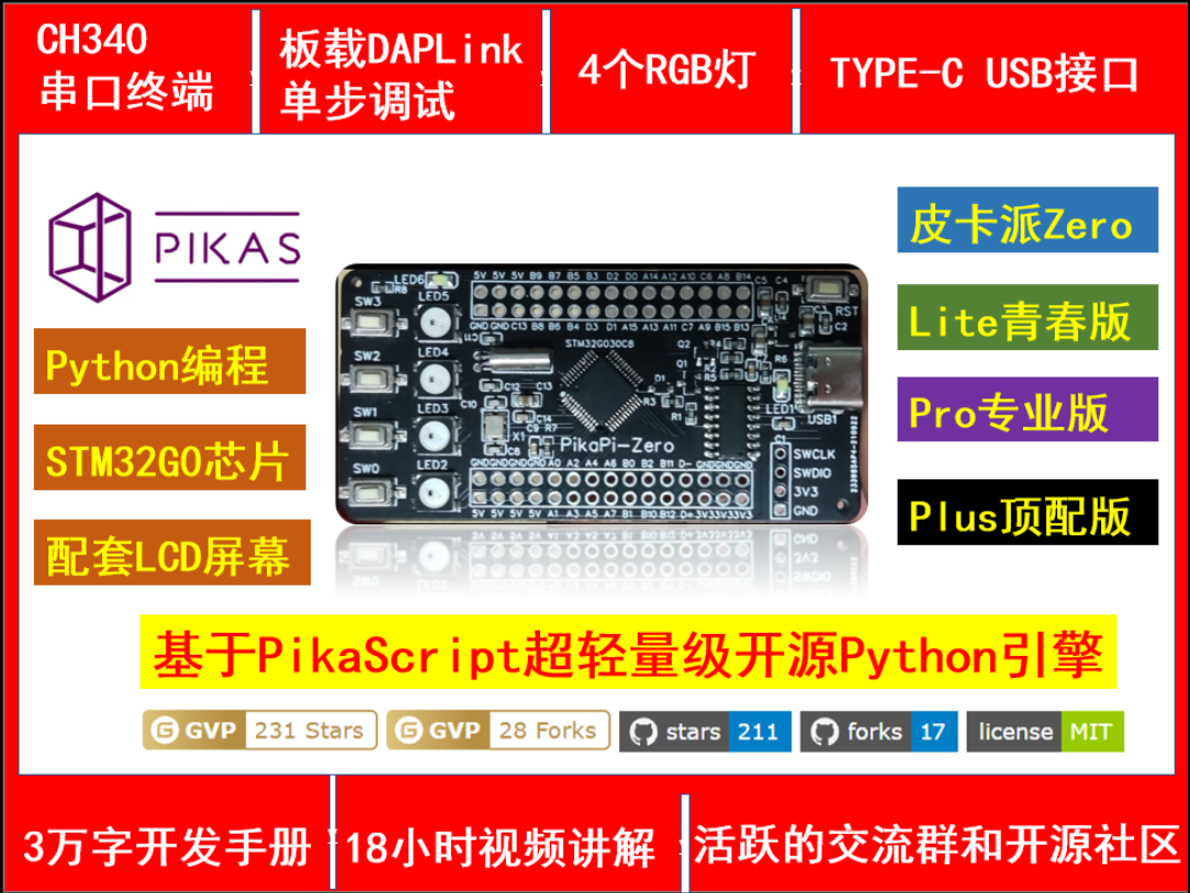
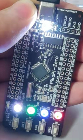
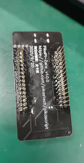
The development board looks like this. It has an STM32G0 chip onboard with 4 colorful RGBs and a Type-C interface.
Optional:
Lite Youth Edition: STM32G030 + CH340 serial port chip 64k flash 8k ram
Pro version: STM32G030 + DAPLink debugger 64K flash 8k ram
Plus top version: STM32G070 + DAPLink debugger 128k flash 32k ram
 This development board is officially supported by the PikaPython project and continues to be updated continuously. The latest kernel and latest functions of PikaPython can be experienced on this development board.
This development board has also been officially adapted by the project with a wealth of peripheral modules, including GPIO, TIME, ADC, IIC, LCD, KEY, PWM and other modules drivers have been developed and can be programmed directly with python.
3.1.2. Video tutorials
https://space.bilibili.com/5365336/channel/seriesdetail?sid=1034902
3.1.3. How to download the Python program for the microcontroller
The download method is very simple, just connect the Type-C data cable.
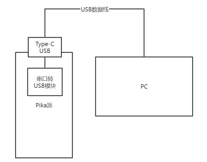
We use a USB data cable to connect the computer and the Pika Pie development board, and we can download the program.
When downloading the program, you need to use a serial port assistant tool. We can use the XCOM assistant developed by Punctual Atom, which can be downloaded from the Punctual Atom forum.
http://www.openedv.com/thread-279749-1-1.html
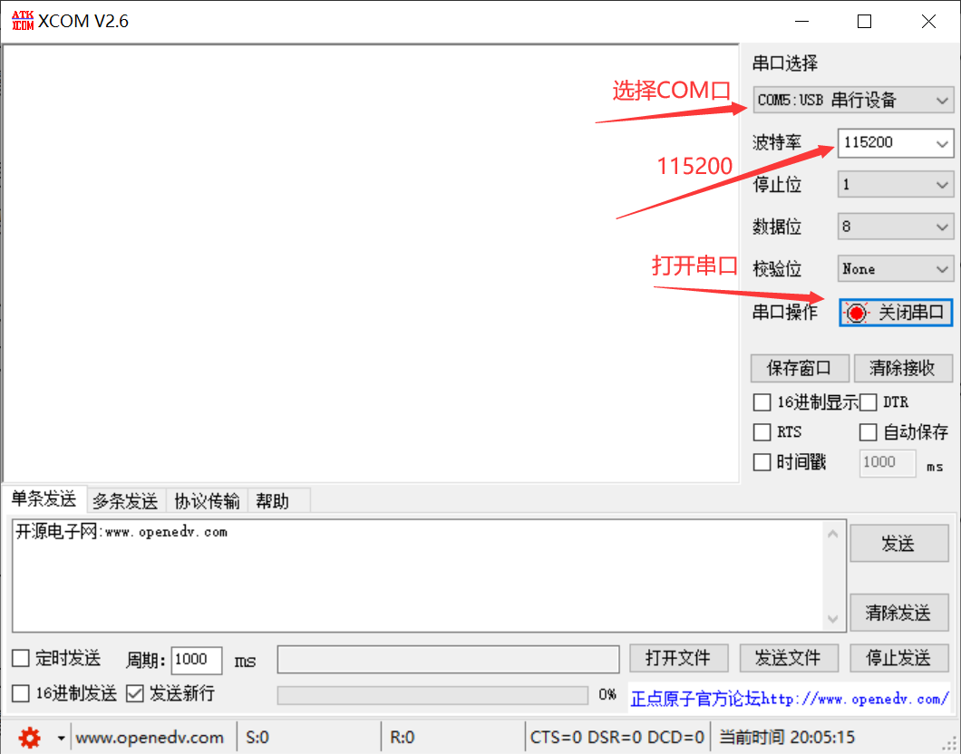
Select the COM port, then select the baud rate as 115200, and then click to open the serial port. At this time, it is connected to the Pika Pie. Simply send a Pthon script file to download the Python program to Pika Pie. To verify that the download was successful, we use the sample Python scripts in the PikaPython source repository.
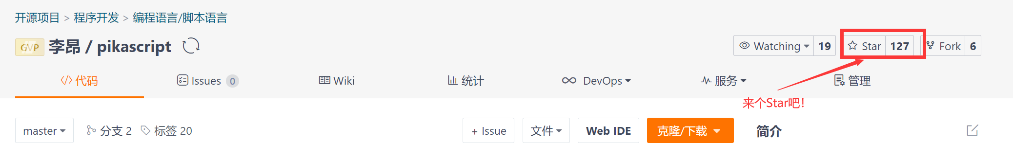
We enter the code repository of PikaPython
https://github.com/pikastech/pikascript
It is customary to click a Star~
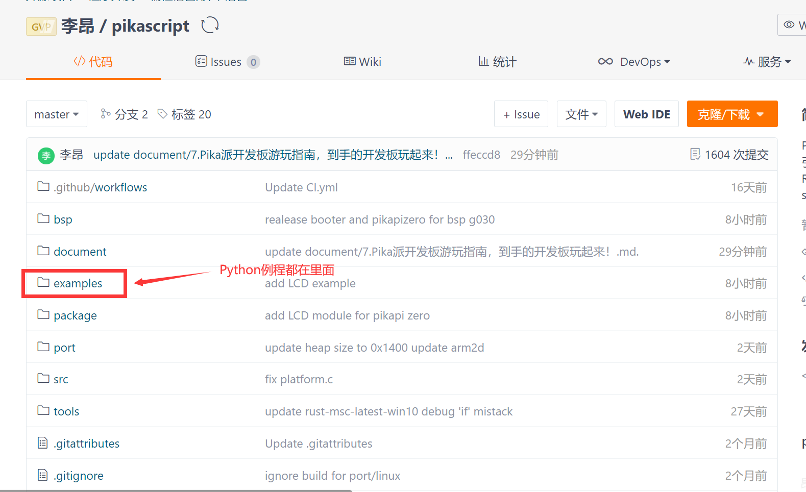
Then we click on the examples folder, which contains the Python routines that can be run.
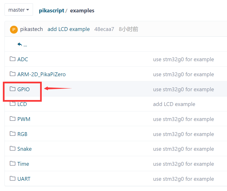
Let’s open the GPIO folder and light up the water lamp to see~
The main.py in the GPIO folder is the sample code for GPIO
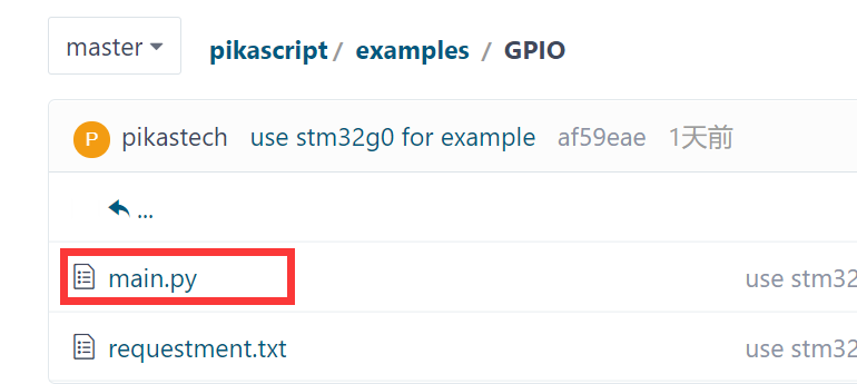
We can open main.py and see~
import PikaStdLib
import machine

mem = PikaStdLib.MemChecker()
io1 = machine.GPIO()
time = machine.Time()

io1.init()
io1.setPin('PA8')
io1.setMode('out')
io1.enable()
io1.low()

print('hello pikascript')
print('mem.max:')
mem.max()
print('mem.now:')
mem.now()

while True:
    io1.low()
    time.sleep_ms(500)
    io1.high()
    time.sleep_ms(500)
Without explaining the content inside, let’s download this script directly.
We also create a new main.py file on the desktop, and then copy this code into it.
We choose this main.py file
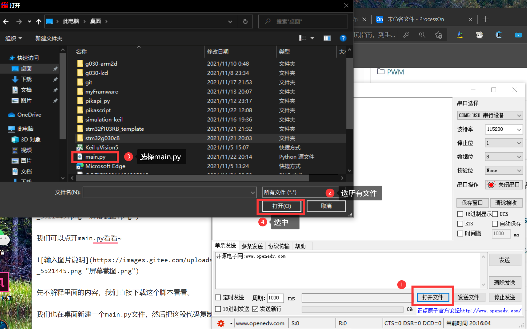
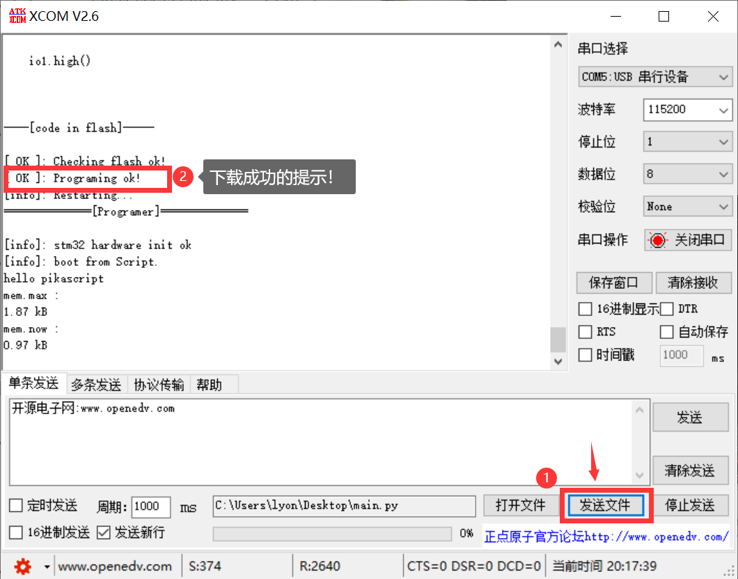
Then click “Send File” to download the script!
We can see the [ OK ]: Programing ok! prompt, which means the download is successful!
At this time, the LED on the development board will flash!
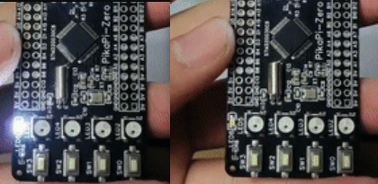
Congratulations on your achievement of playing Python with a microcontroller!
3.1.4. What is written in the GPIO script?
Let’s parse this GPIO routine line by line.
import PikaStdLib
import machine
The first line is the first and second line, which means that two modules are imported, one is the PikaStdLib module and one is the machine module. PikaStdLib is the standard library of PikaPython, which has some system functions, such as checking the memory usage. In the fourth line, we create a new mem object whose class is PikaStdLib.MemChecker().
mem = PikaStdLib.MemChecker()
This class has a max() method and a now() method. Using these two methods, you can print out the memory size currently used by PikaPython.
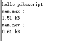
print('hello pikascript')
print('mem.max:')
mem.max()
print('mem.now:')
mem.now()
We can look at the printout of the serial port, we can see that the maximum memory usage is 1.51kB, and the current memory usage is 0.61kB, is it very small!
 screenshot.png
The time object is newly created through the Time() class of machine and can provide basic delay functions.
time = machine.Time()
Through the time.sleep_ms() method, you can delay in milliseconds. For example, the function of the following code is to delay 500ms.
time.sleep_ms(500)
io1 is our protagonist today. This is a GPIO object, which is newly created with the machine .GPIO() class.
io1 = machine.GPIO()
After creating a new io1 object, we need to initialize this io, init() is used for object initialization, used at the front, and then setPin(’PA8’) means using the PA8 port setMode(’out’) means using the output mode, And enable() means to start the hardware of io1, and low() pulls down the level of io1. A led light on the Pika Pie is connected to the PA8. As long as you control the level of the PA8, you can control the light on and off.
io1.init()
io1.setPin('PA8')
io1.setMode('out')
io1.enable()
io1.low()
In the main loop of the program, switch the high and low levels of io1 to make the LED flash~
while True:
    io1.low()
    time.sleep_ms(500)
    io1.high()
    time.sleep_ms(500)
3.1.5. Interpretation of other Python routines
3.1.5.1. ADC
Let’s interpret other routines in examples, such as this ADC routine, which is to read the analog voltage value on the PA1 pin, and then print it out~
import PikaStdLib
import machine

time = machine.Time()
adc1 = machine.ADC() #Create a new ADC object

adc1.init() #Initialize ADC object
adc1.setPin('PA1') #Set the pin
adc1.enable() #Start the hardware

while True:
    val = adc1.read() #Read the value of ADC once and store it in the val variable
    print('adc1 value:') #Print what is read
    print(val)
    time.sleep_ms(500) #Wait for 0.5s
3.1.5.2. UART
The following is the routine of the serial port, the function is to read the received two bytes, and then print them out
import PikaStdLib
import machine

time = machine.Time()
uart = machine.UART() #Create a new serial port object
uart.init()
uart.setId(1) #Set the serial port number, use serial port 1
uart.setBaudRate(115200) #Set the baud rate
uart.enable() #Start hardware

while True:
    time.sleep_ms(500)
    readBuff = uart.read(2) #read two characters
    print('read 2 char:')
    print(readBuff) # print out
3.1.5.3. PWM
The following is the PWM routine, you can specify the pin to output the PWM wave, you can set the frequency and duty cycle
import PikaStdLib
import machine

time = machine.Time()
pwm = machine.PWM()
pwm.setPin('PA8') #Set PWM output pin
pwm.setFrequency(2000) #Set the frequency
pwm.setDuty(0.5) #Set the duty cycle to 50%
pwm.enable()

while True:
    time.sleep_ms(500)
    pwm.setDuty(0.5)
    time.sleep_ms(500)
    pwm.setDuty(0.001) #Set the duty cycle to 0.1%
3.1.5.4. RGB
Then the following is the RGB routine~
import machine

import PikaStdLib

time = machine.Time()
adc = machine.ADC()
pin = machine.GPIO()
pwm = machine.PWM()
uart = machine.UART()
rgb = machine.RGB() #Create a new RGB object
mem = PikaStdLib.MemChecker()

rgb.init() #Initialize the object
rgb.enable() #Start hardware

print('hello 2')
print('mem used max:')
mem.max()

while True:
    print('flowing')
    rgb.flow() #RGB water light flow
This routine can drive the onboard 4 RGB water lights~
3.1.5.5. LCD
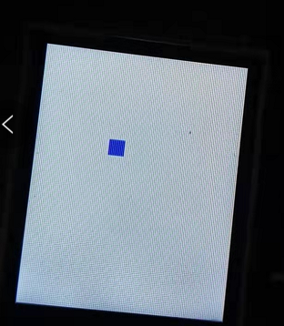
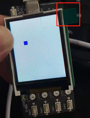
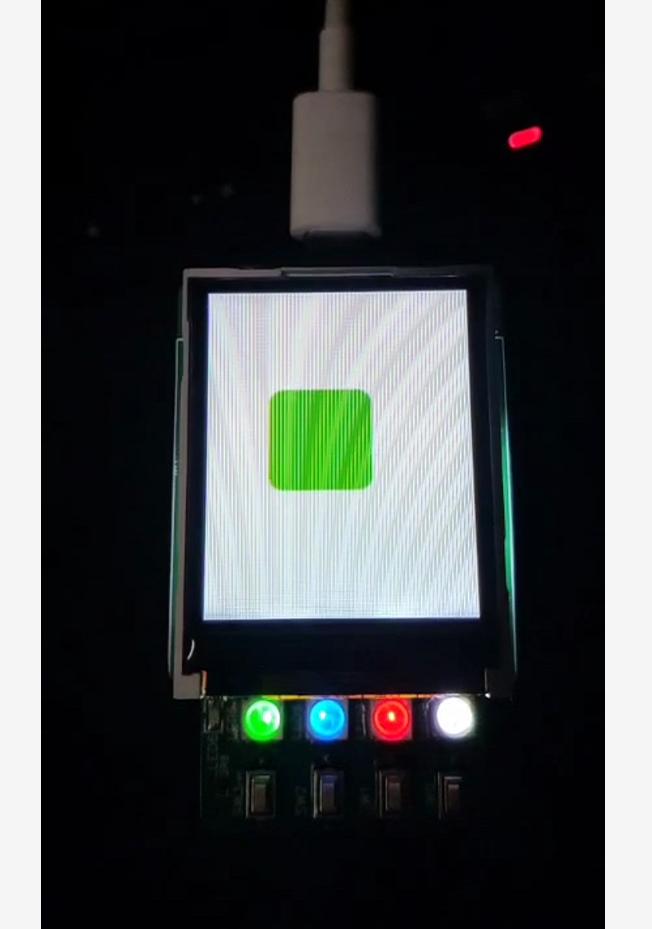
There is also an LCD routine that can display a small square on the LCD, and you can use the four onboard buttons to control the movement of the small square~
from PikaObj import *
import PikaStdLib

import machine

lcd = machine.LCD()
lcd.init()
lcd.clear('white') #Initialize LCD background fill with white
mem = PikaStdLib.MemChecker()
key = machine.KEY() #Create a new key object and get the onboard key input
key.init()
time = machine.Time()
h = 10
w = 10
x = 10
y = 10 # used to represent the height, width and coordinates of the small square
x_last = x
y_last = y #Record the last position for erasing
is_update = 0 #Control the flag variable that refreshes the screen
print('mem used max:')
mem.max()
lcd.fill(x, y, w, h, 'blue') # draw small blue squares
while True:
    key_val = key.get() # get the value of the key
    if key_val != -1:
        x_last = x
        y_last = y
        is_update = 1 #Start refresh
    if key_val == 0:
        x = x + 5 #change the coordinates of the small square
    if key_val == 1:
        y = y - 5
    if key_val == 2:
        y = y + 5
    if key_val == 3:
        x = x - 5
    if is_update: #Refresh the screen
        is_update = 0
        lcd.fill(x_last, y_last, w, h, 'white') #Erase the previous position
        lcd.fill(x, y, w, h, 'blue') # draw a new position
When you are familiar with the LCD driver, you can try to develop your own mini-games~
3.1.6. run interactively
After main.py is executed, it will enter the interactive operation, so as long as the while True : in main.py is canceled, so that it can complete the execution and exit, you can enter the interactive operation.
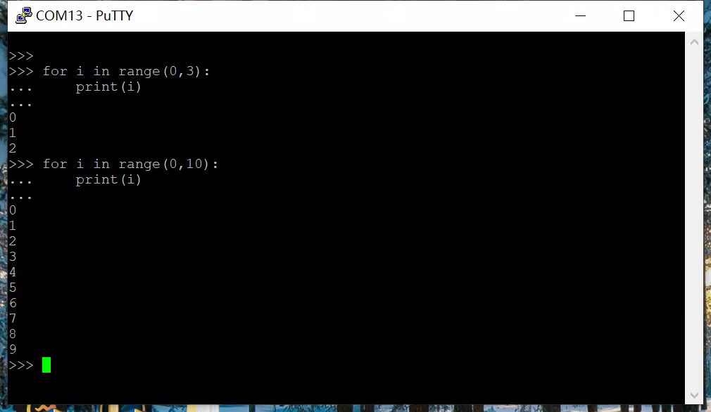 Interactive execution supports single-line and multi-line input, consistent with general Python usage. It is recommended to use PuTTY serial terminal.
Entering
Interactive execution supports single-line and multi-line input, consistent with general Python usage. It is recommended to use PuTTY serial terminal.
Entering exit() will directly restart the system.
Precautions:
The firmware version needs to be no less than **v1.3.2. **
If using the PuTTY terminal does not work, use XCOM.
All English input methods should be used in the terminal.
Indent should use 4 spaces, do not use the TAB key.
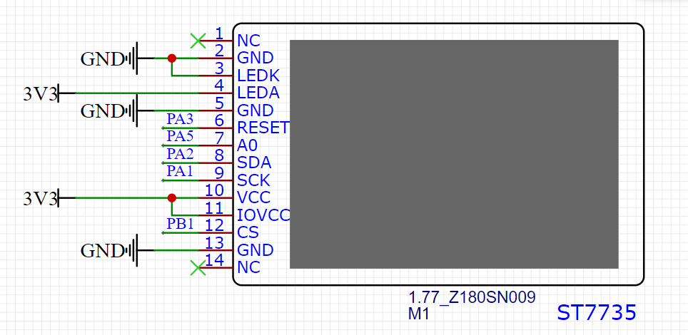
3.1.7. LCD screen installation
Refer to the figure below to solder the long pin headers
Plug in the screen, refer to the direction of the green flag, if the screen can be lit, it means that the direction of the plug is correct, if it is plugged in reversely, it will not light up.
3.1.8. Firmware upgrade
The firmware of Pika Pie is updated on a rolling basis, and new firmware versions will be released continuously to provide new functions, and some new functions can only be played by upgrading the firmware, so it is also very important to learn to upgrade the firmware~
3.1.8.1. Compile the firmware yourself
The firmware is a Keil project and compilation is very simple.
Download the firmware project:
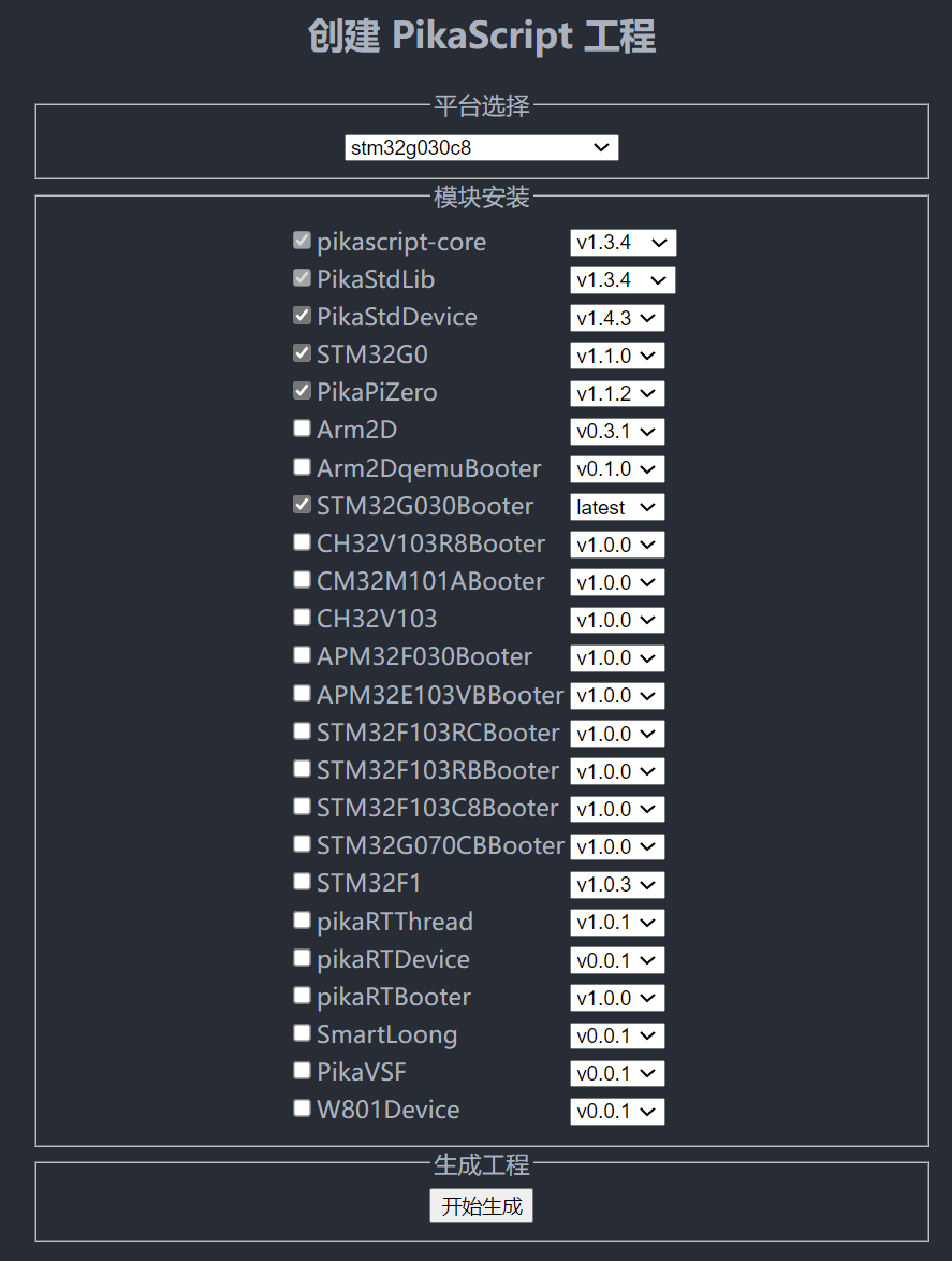
Enter pikascript official website http://pikascript.com
The Lite and Pro versions use the stm32g030 platform.
The Plus version uses the stm32g070 platform.
Then click “Start Generation”.
(The default module will be automatically selected after selecting the platform)
 Just open the Keil project and compile it.
When compiling, you need to use Keil not lower than V5.36, which needs to be activated.
Just open the Keil project and compile it.
When compiling, you need to use Keil not lower than V5.36, which needs to be activated.

The compiled .bin is in MDK/stm32g030c8/stm32g030c8.bin .
3.1.8.2. Download the compiled firmware directly
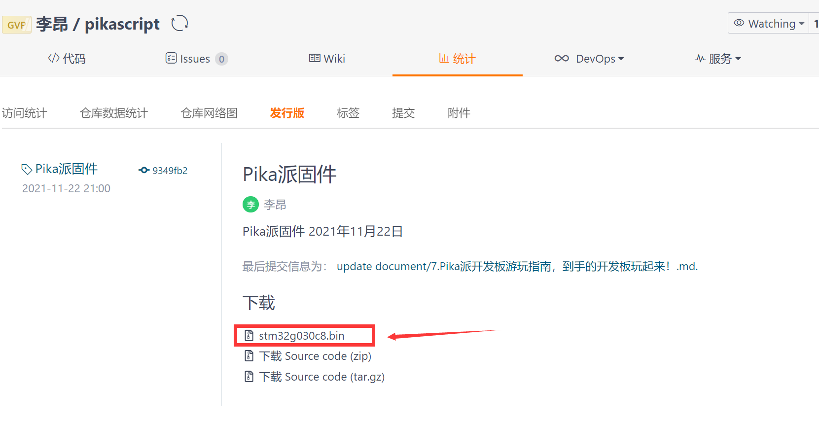
If you want to use the ready-made firmware, you can also download the compiled one directly~
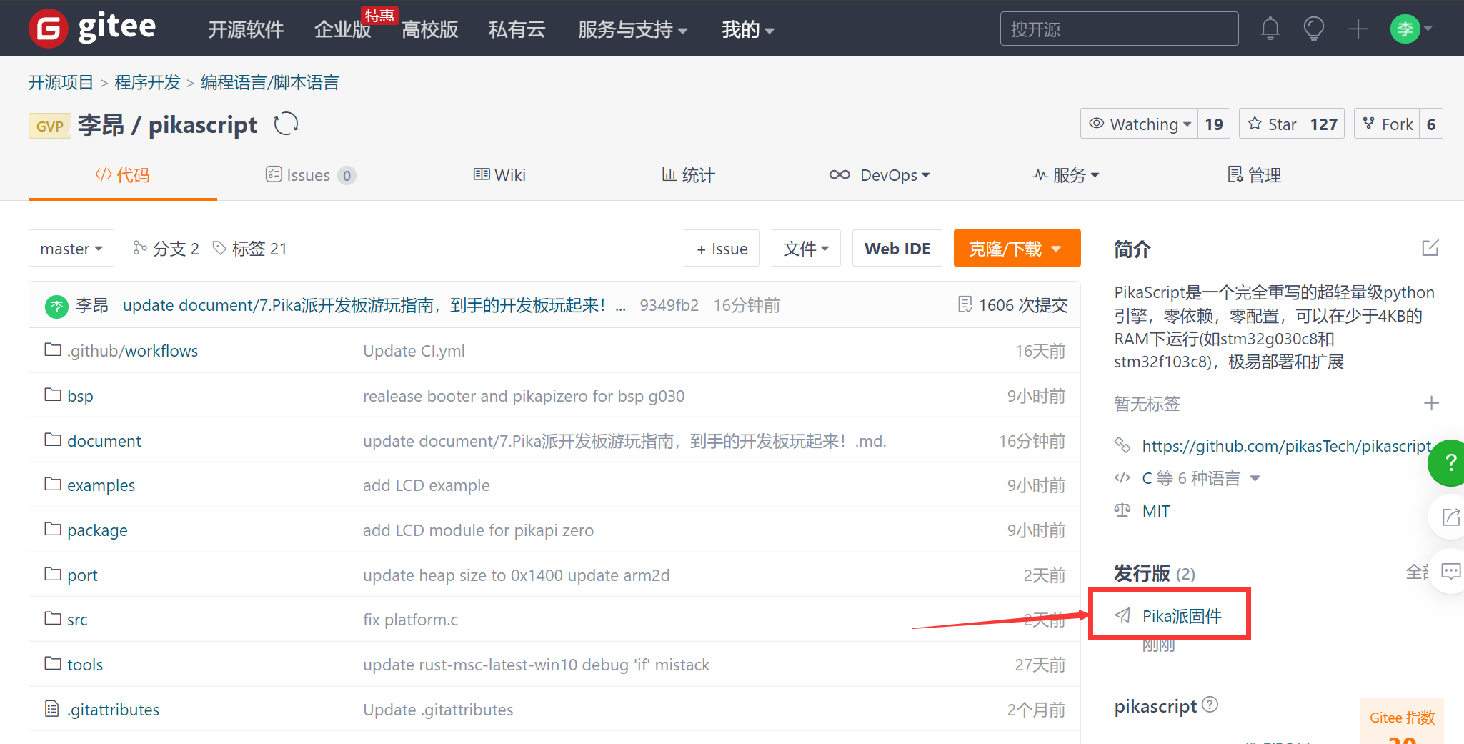
Click to download to get the latest firmware~
3.1.8.3. Serial Bootloader upgrade
To upgrade the firmware, you can also use the serial port. When upgrading, you need to use the firmware compiled by yourself or the .bin firmware you downloaded directly. Currently, the versions that support serial bootloader upgrade are:
Lite Youth Edition
Pro Professional Edition
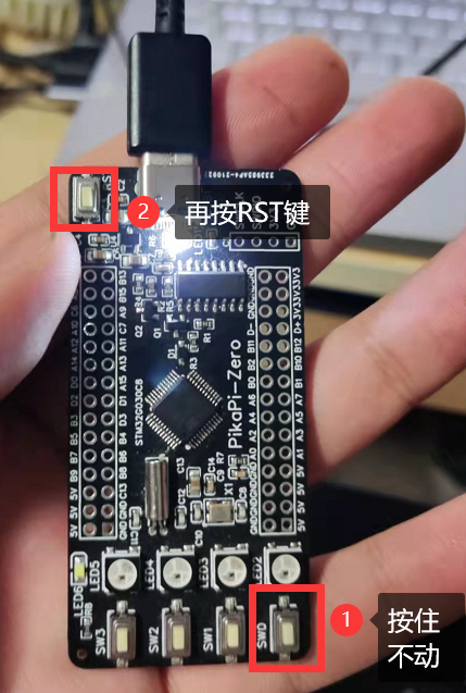
Next, we need to let the pika pie enter the upgrade mode. We press and hold the SW0 key on the development board and press the RST key at the same time to enter the upgrade mode.
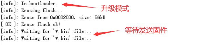
In the upgrade mode, we can see the prompt information of the serial port
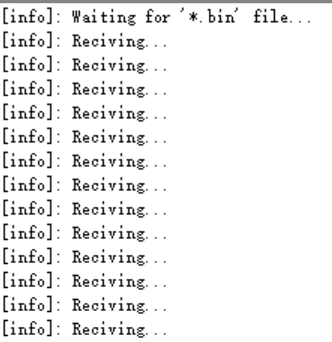
Then we use the serial port assistant to select the stm32g030c8.bin file just downloaded and send it through the serial port. After the firmware is recognized, Reciving….
After sending, press the RST key to restart, and the upgrade is complete! If it can be started normally, then the upgrade is successful.
3.1.8.4. Upgrade using SWD
The Lite version can connect to J-Link \ DAP-Link \ ST-Link to upgrade SWD.
The Pro version and Plus version have onboard DAP-Link, which can be upgraded by SWD directly by connecting to USB.
The Lite and Pro versions use the bsp/stm32g030 project.
The Plus version uses the bsp/stm32g070 project.
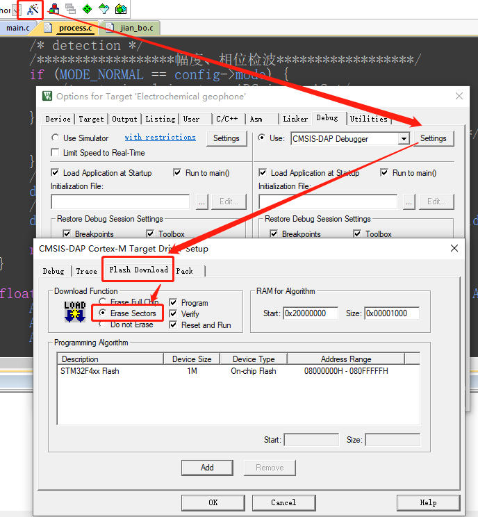
When using SWD to upgrade, the download method of “Partial Erase” should be selected
3.1.8.5. Download Python program using firmware
The firmware loads pikascript/main.py as the default Python program when compiled. Before downloading the firmware, after pressing SW0 + RST to erase the flash, it will boot from the firmware Python program.
3.1.9. ARM-2D GUI engine
pika pie supports running ARM-2D GUI engine
Instructions:
Obtain the bsp/stm32g030 project.
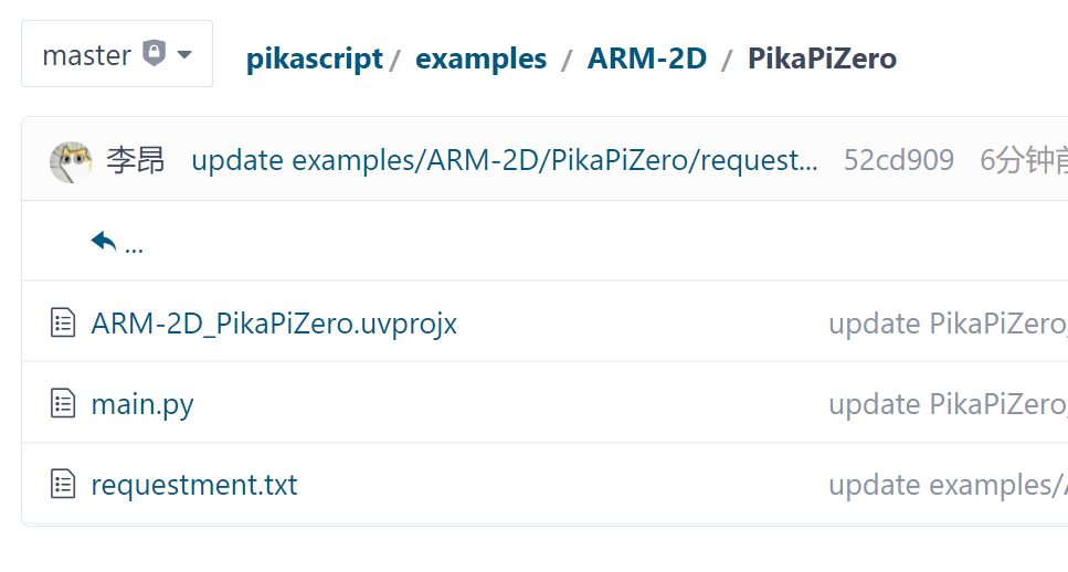
Use the project files in examples/ARM-2D/PikaPiZero, replace main.py and requestment.txt.
Press and hold the SW0 key on the development board and press the RST key at the same time to erase the flash.
Re-run the package manager, precompile, compile the project, and flash the project using SWD/Bootloader.
3.1.10. common problem
1 Press sw0 + rst to enter the upgrade mode: The first batch of boards shipped did not have the bootloader. You need to manually flash it once. Use jlink / stlink / DAPlink, etc., and flash into pikascript/bsp/pikapizero/bootloader. 2 Cannot enter the bootloader / Suspected to be stuck and unable to run: Check the serial port assistant, you cannot use dtr / rts control, it is recommended to use the xcom assistant of punctual atom. 3 Download python script stuck: When downloading the python program for the first time, do not download the LCD program, first download a gpio program, and then download the LCD program. In other cases, the download is stuck, and you can restart the download again. If it still doesn’t work, re-flash the firmware and download it again. 4 Project compilation error, missing files: The project needs to pull modules and precompile remotely. You need to run pikascript/pikaPackage.exe and pikascript/rust-msc-win10-latest.exe before compiling the project.
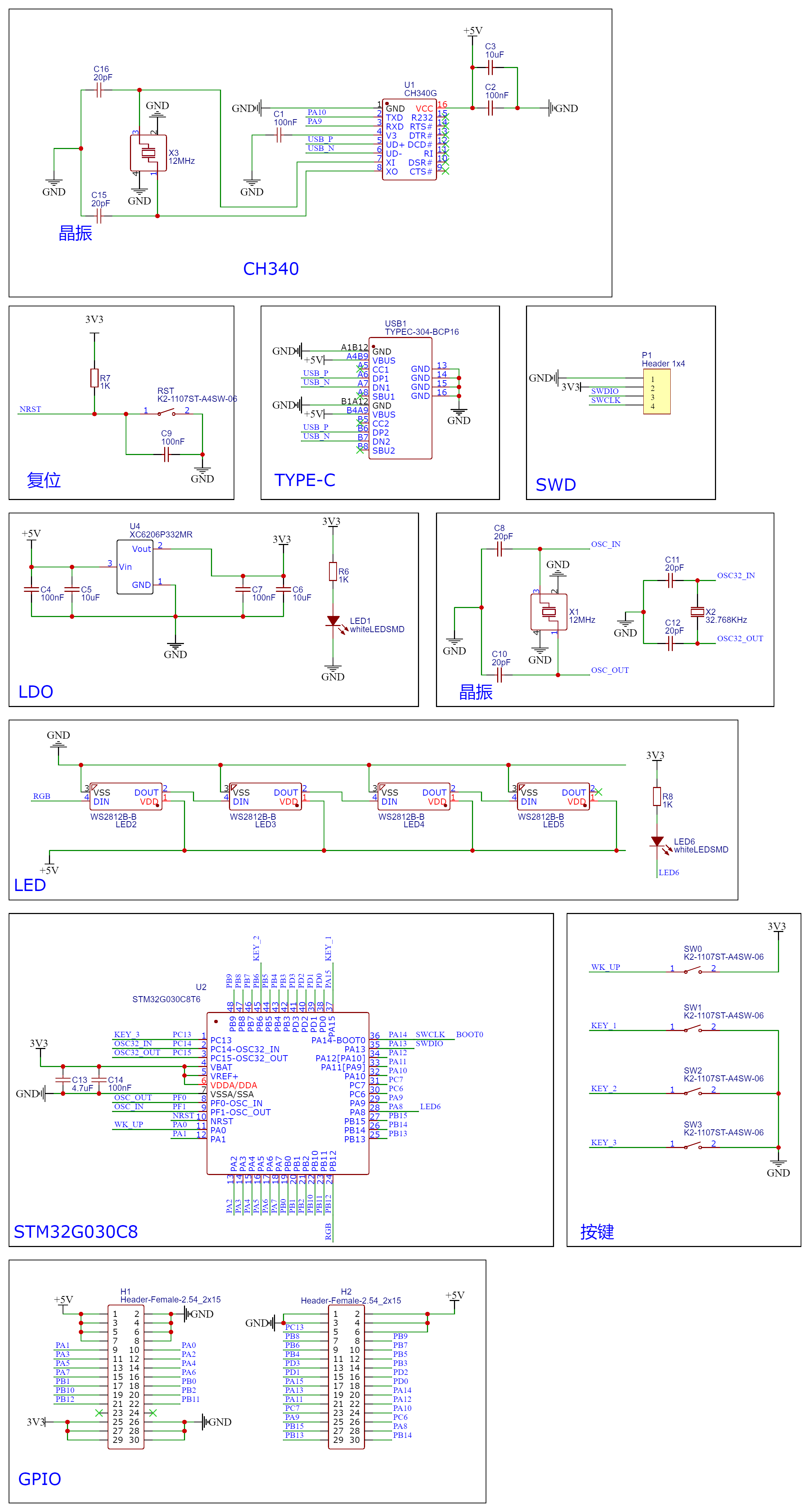
3.1.11. Schematic
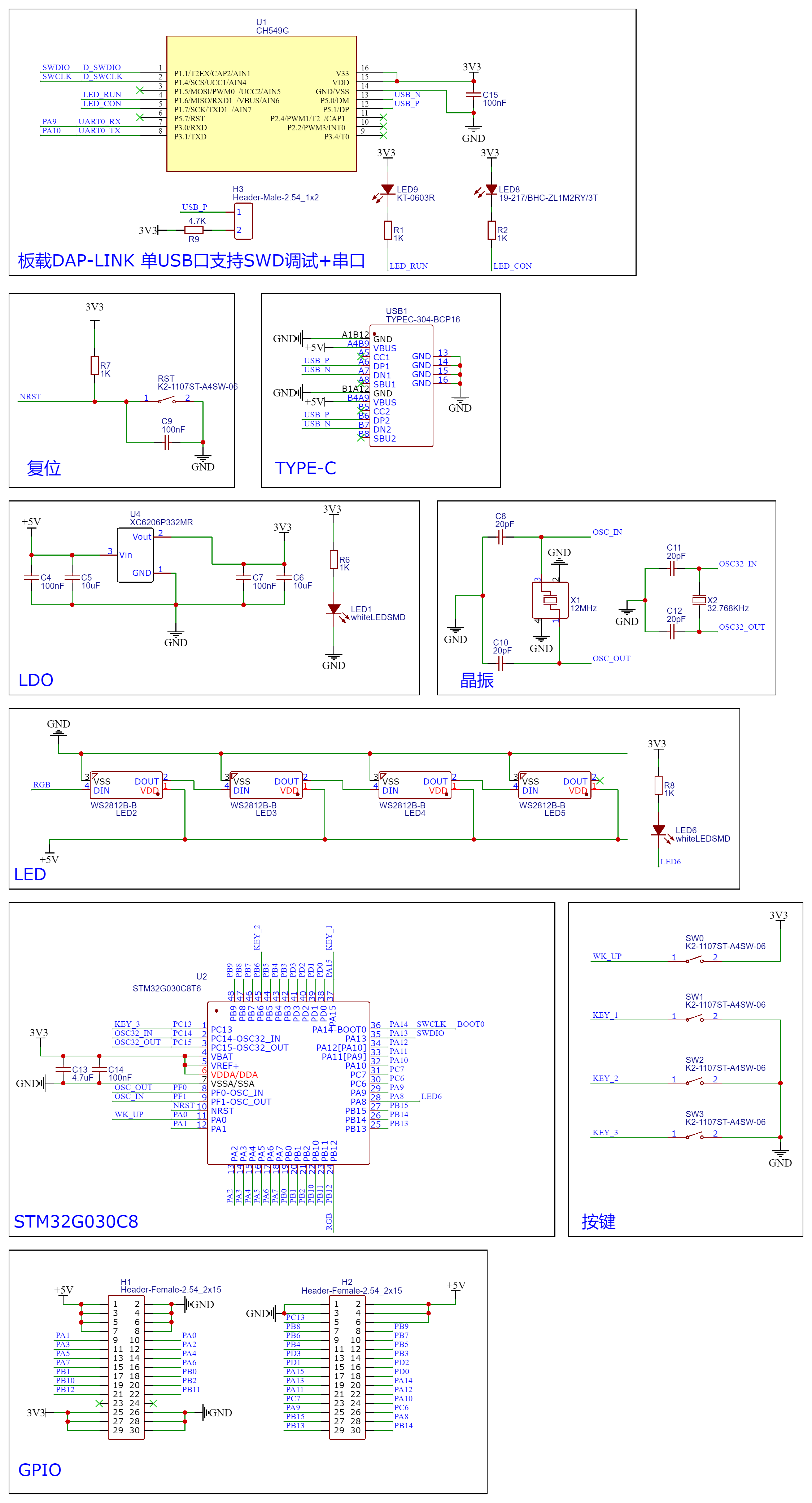
3.1.11.1. Lite Youth Edition
3.1.11.2. Pro Professional Edition
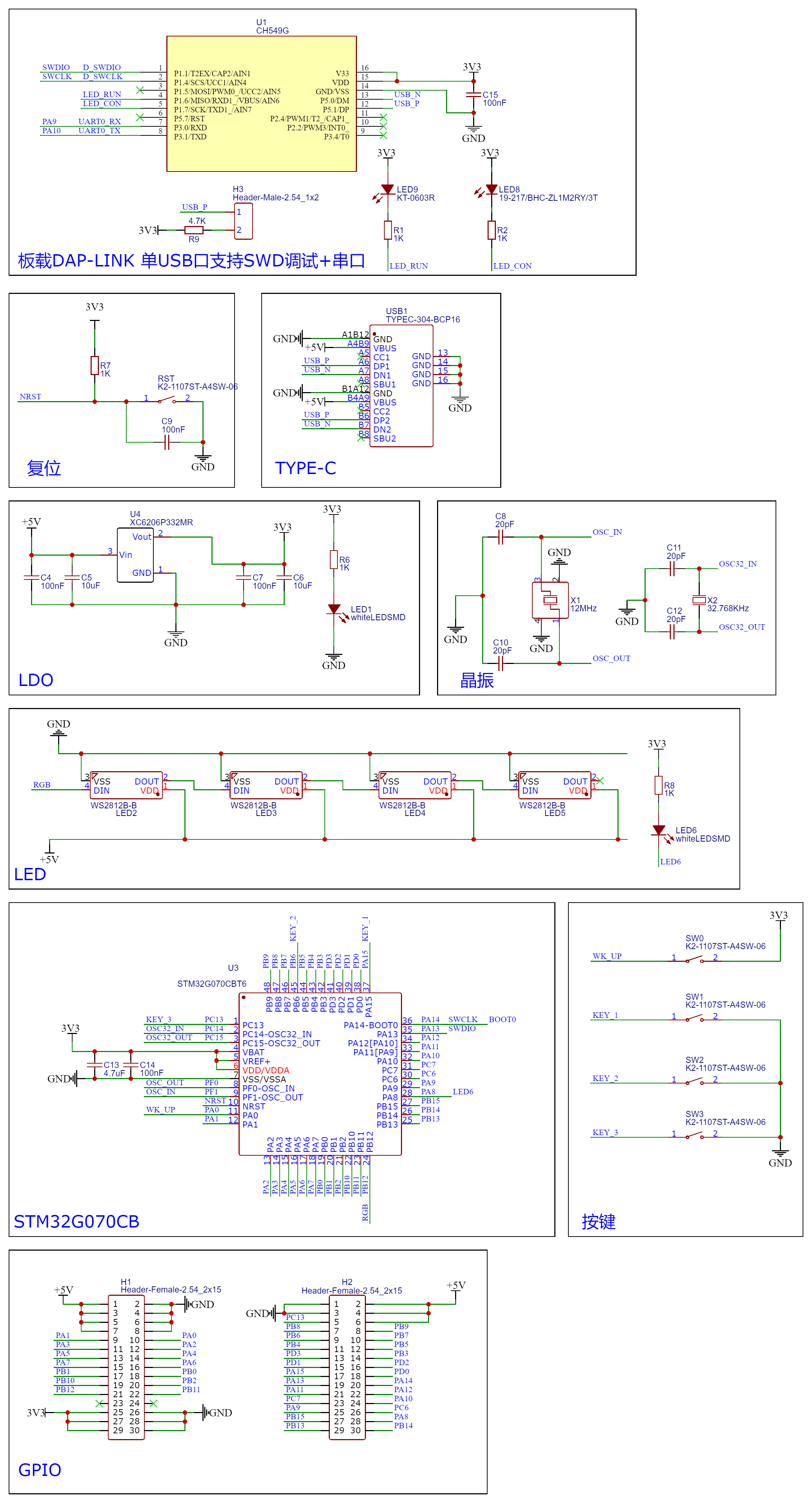
3.1.11.3. Plus top version
3.1.11.4. LCD